44 Results
View results:
Sort by:

The new generation of RFEM software is an intuitive, powerful, and easy-to-handle 3D FEA program that meets all the latest demands in modeling, calculation, and structural design. The modern design concept, as well as the introduction of new features, make the program even more innovative and user-friendly. The main differences between RFEM 6 and its previous version, RFEM 5, are discussed in the following text.

In the age of BIM, data exchange between the various disciplines of structural engineering is becoming increasingly important. Since each software has its own specifications with regard to the description of cross-sections and materials, RFEM and RSTAB offer a conversion table (mapping file).

For a quick overview of the cross‑sections used, you can show the members in color sorted by cross‑section. Use the right mouse button in the work window to select "Colors in Graphics According to" → "Cross -Sections" from the shortcut menu. In the current program versions, you can use a panel with an editable color scale for this.
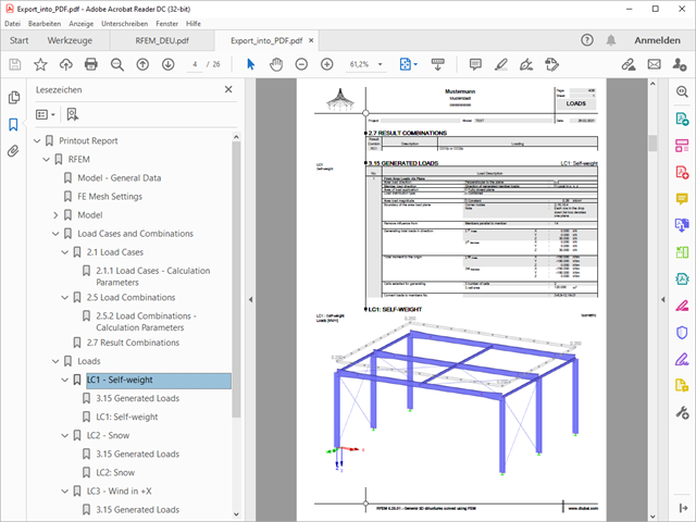
A PDF version of the printout report can be created in two ways. The most common way is to use a PDF printer that must be previously installed. The printer will be controlled like a real printer.
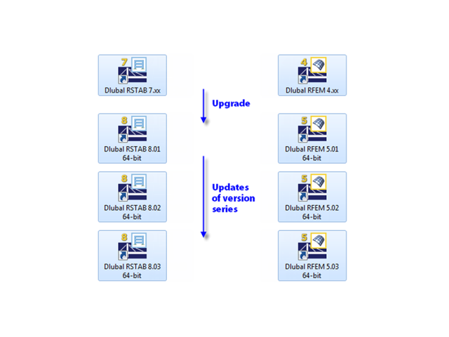
When updating within a version series (for example, RFEM 5.01.01 to 5.01.02), the old program files are removed and replaced by new ones. The project data, of course, remain unchanged. When updating to the next version series (for example, RFEM 5.02.01), the new version is installed in parallel. The program files are located in different directories, so the previous version is still available.
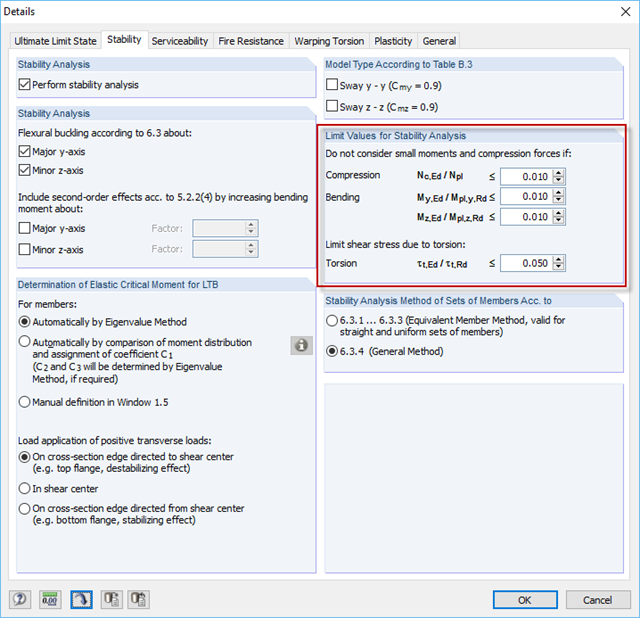
As of the program version X.11, the filter options of small compression forces or moments for stability analysis in RF‑/STEEL EC3 have been revised. The revision of these filter options in the "Stability" tab of the "Details" dialog box allows you to work in the module transparently, since they are now independent of the design.
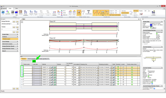
With program version RFEM 5.06, you can edit several tendons in the RF‑TENDON add‑on module simultaneously. To do this, it is necessary to select the corresponding tendons in the tendon arrangement table.
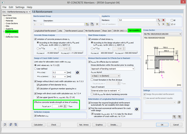
As of program version 5.06, you can use the option to adjust the effective concrete tensile strength fct,eff,wk at the time of cracking. At the start of the SLS design, the program checks whether the internal forces can cause cracks in the concrete. For this, the effective concrete tensile strength at the time of cracking is applied. You can adjust the strength via the factor. The calculation details display the adjusted value.
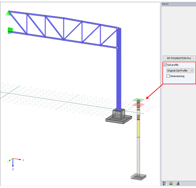
With version x.06.1103, the input of a soil profile was introduced in RF-/FOUNDATION Pro.
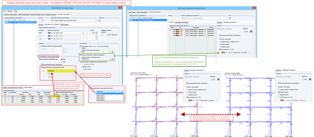
In RF-/DYNAM Pro – Equivalent Loads, a signed result option in accordance with the dominant eigenmode has been available since version X.06.3039. For the modal combination of results corresponding to the single eigenvalues, a quadratic combination rule has to be used. In RFEM and RSTAB, the SRSS and the CQC rule are available. Only results, not loads, are allowed to be combined directly. The reason is the mode shapes, which are arbitrarily scaled and signed.
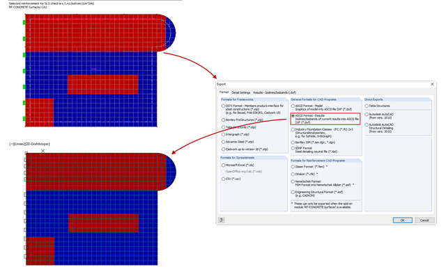
Until program version RFEM 5.06.1103, it was only possible to export the results on surfaces in the form of isolines into a DXF file. With program version 5.06.3039, you can now also export the results in the Isobands display option.
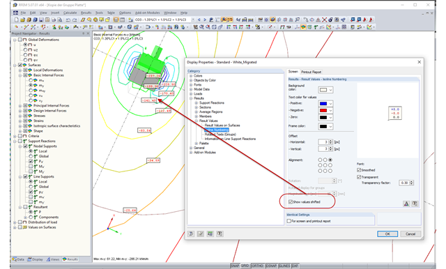
In the case of very small distances between isolines, the labels often overlap, which makes the result documentation difficult. As of RFEM version 5.06, you can select a shifted arrangement of the isoline labels in the Display Properties dialog box. By selecting the "Show values shifted" option, you can easily avoid overlapping the result values in many cases.
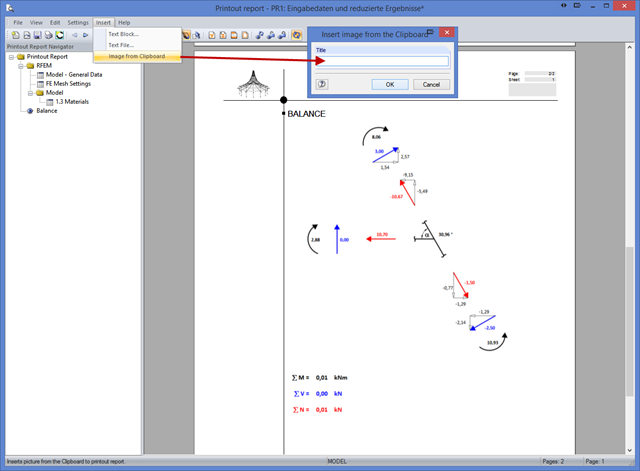
With program version x.06, you can also insert .bmp file formats from the clipboard into the printout report. Previously, only the .emf format (Windows Metafile) was supported. Thus, it is no longer necessary to insert a screenshot in a supported program (such as MS Paint) and go from there to the printout report.
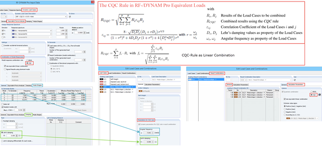
In RF‑/DYNAM Pro – Equivalent Loads the CQC (Complete Quadratic Combination) rule has been available since version X.06.3039.
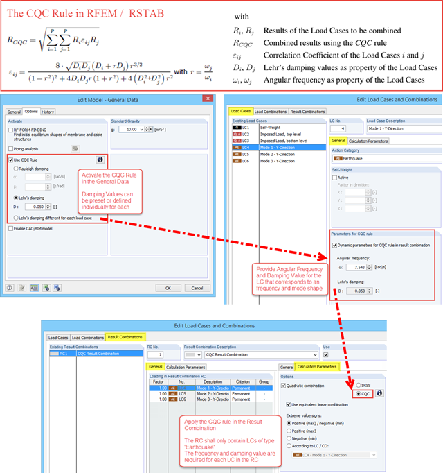
The CQC (Complete Quadratic Combination) rule has been available in RFEM and RSTAB since version X.06.3039. In the General Data of the model you can activate the CQC rule, and for Load Cases of the "Earthquake" type two new properties are available: "Angular frequency" and "Lehr's damping".
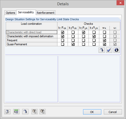
With program version 5.06, RF‑CONCRETE Surfaces and RF‑CONCRETE Members perform serviceability limit state designs automatically according to the design situation of the calculated load cases, load combinations, and result combinations.

With RFEM 5.06 and RSTAB 8.06, the examples and help files for programming the COM interface are not only available on the Internet, they are also included in the installation. To find them, look for the "SDK" folder in the project directory (usually C:\Users\Public\Documents\Dlubal).
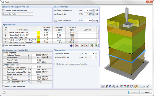
As of program version x.06.1103, you can enter a soil profile in RF‑/FOUNDATION Pro. This gives you the advantage of setting several soil layers with different soil parameters above and below the foundation base. To enter the soil layers, there is a library with various soil types that can also be extended with user‑defined soils. The user-defined soil profile is shown in an interactive information graphic. Any change (for example, a soil thickness modification) is reflected in the graphic immediately.
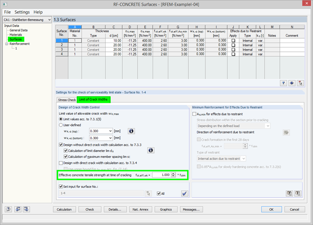
As of RFEM Version 5.06, there is the option in RF‑CONCRETE Surfaces to adjust the effective concrete tensile strength at the time of cracking. At the start of the SLS design, the program checks whether the internal forces can cause cracks in the concrete. For this, the effective concrete tensile strength at the time of cracking is applied. You can adjust the strength via the factor. The calculation details display the adjusted value.

With RFEM version 5.06, member stiffnesses can be influenced by methods that are aligned with US steel construction standard ANSI/AISC 360-10. According to this standard, reduction factor τb must be considered for the determination of internal forces in all members of which the flexural resistance contributes to the model's stability. This coefficient depends on the axial force in the member: The larger the axial force, the larger τb is.

Various optimizations are available with program version x.06.1103. The RF-/FOUNDATION Pro add-on module has also been subjected to further development.
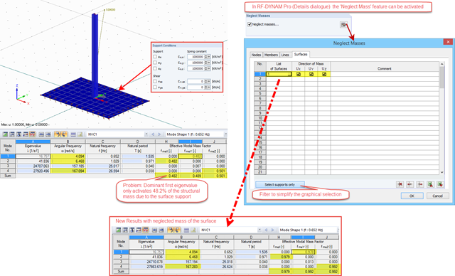
As of the version 5.06.1103, masses of nodes, lines, members, and surfaces can be neglected in RF‑DYNAM Pro. The setting to activate this feature can be found in the Details dialog box; the neglected masses are valid for all defined mass cases.
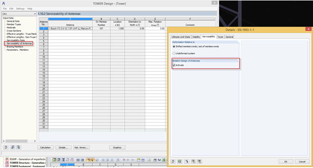
As of program version X.06.1103, you can perform serviceability limit state design checks of antennas in RF‑/TOWER Design. You can activate this function under [Details] → "Serviceability". Then, the limit values can be adjusted in Window 1.10.2, Serviceability of Antennas.
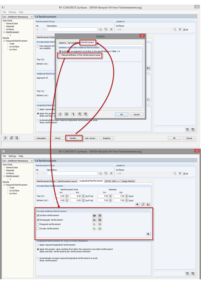
As of program version RFEM 5.06, you can not only perform the automatic arrangement of an additional reinforcement, but also define the surface reinforcement manually. In addition to the uniformly distributed basic reinforcement, you can define various surface reinforcements (per surface; rectangular, circular, or polygonal).

As of the program version X.06 of the RF‑/TIMBER Pro, RF‑/TIMBER AWC, and RF‑/TIMBER CSA add‑on modules, notches and cross‑section reductions can be considered in the design. The procedure is as follows:
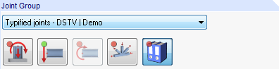
Starting with program version X.06, joint groups are clearly identified in RF‑/JOINTS.
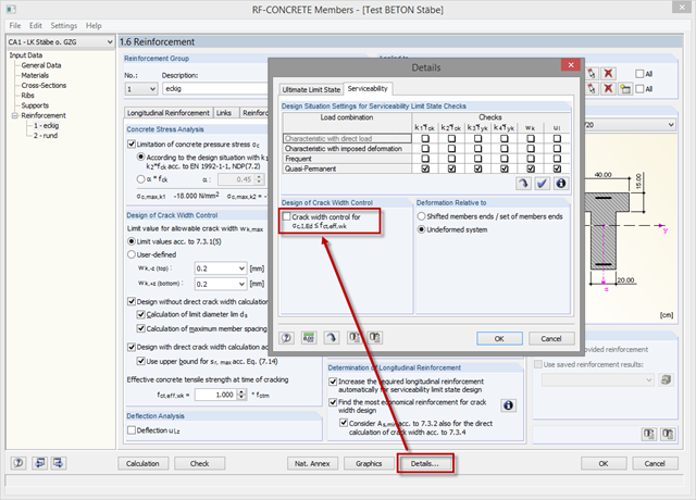
Starting with program version X.06, you can set in RF‑CONCRETE Members or CONCRETE whether the crack width analysis should be performed in any case, or only when exceeding the effective tensile strength of concrete.

RF‑/FOUNDATION Pro introduced the geotechnical design of single foundations according to EN 1997‑1 in RFEM 5 and RSTAB 8. Depending on the National Annex preset in the add‑on module, you can determine the bearing resistance using Approach 2 or 3 in compliance with EN 1997‑1 up to Version x.04.0108.
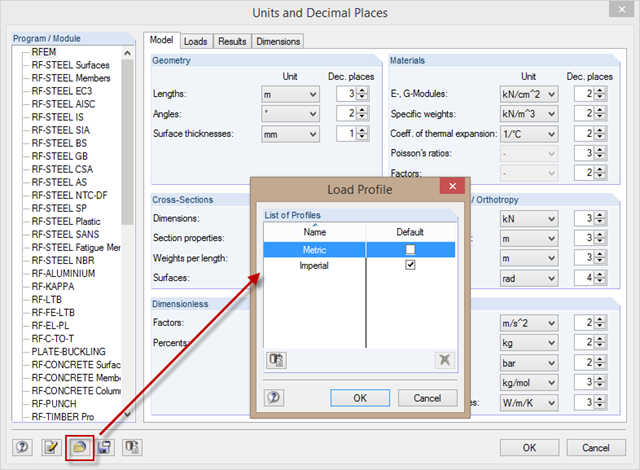
When changing the units from the metric to the imperial measurement system, it is not necessary to change all the units individually. To do this, corresponding unit profiles are available in the "Units and Decimal Places" dialog box, which you can activate as shown in the picture.
RFEM and RSTAB provide numerous interfaces with other programs for data exchange. In the respective programs, different names are often used for the same materials and cross-sections. Therefore, it is necessary to convert the material and cross‑section names in order for them to be recognized by the program after the data exchange.